Assembly and Adjustment
Dave Tutelman & Dan Neubecker -- March 23, 2005
Before assembling your NF4, now is be the time to finish the wooden
pieces. This includes sanding, clear-finishing, and staining if you are
so inclined. A good hard polyurethane finish will help its longevity,
as well as make it look better.
For the steps below, consult the "Component Assemblies"
document, which is part of the Plans file. For each bolt on the NF4, it
lists everything that goes on the bolt, in the proper order.
Where there is a photo or diagram that could help, there is a link to it that looks like this: Illustration
Backer board
-
Measure and mark location for installing rotator board stop, but do not mount it yet
-
Install glide feet in legs and level legs
-
Screw legs to backer board
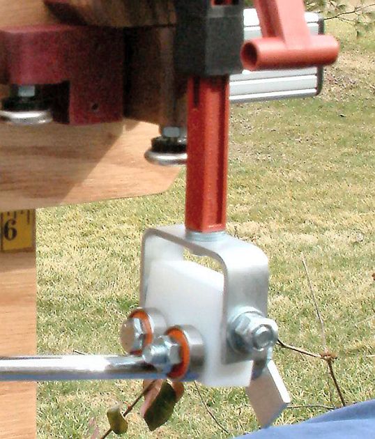
- Install pivot bolt assembly
-
Add UHMW tape. Cut two holes to clear out the holes for the carriage bolts
- Add cam clamp assemblies, including the carriage bolts
- Add
aluminum T-slot rail. Experiment with the position of each of the
carriage bolts in the T-slot, so you get the throw you want from the
cam clamps. There are a lot of positions that will work, but the "best"
position seems to be a personal thing. Dan like the throw from back to
front, with a sort throw to clamp it. Dave prefers a mostly
side-to-side throw, and a more tactile "lock" position.
-
Install t-slot ball knob (if needed)
- Add
Toggle board bolts and t-nuts to t-slot. Do not tighten any more than
needed to keep them in place. Later, you will tighten them at the exact
right place on the rail.
Rotator board stop
-
Install glide foot for adjustment
-
Install stabilizer bearing assembly, finger-tight. You may need to adjust it once the rotator board is in place.
-
Screw rotator board stop to backer board
Bearing arms
- Assemble the front bearing arm with bearings, tip guide, and counterweight. (Illustration)
- Assemble the middle bearing arm with bearings. (Illustration)
- Assemble the rear bearing arm with bearings, shaft marking guide, and counterweight. (Illustration)
Digital scale
(Skip this section for the NeuFinder 4.1 or later. It only applies to the original NF-4, which uses a digital fishing scale.)
- The scale may have a solid ring on top and hook on the bottom.
Remove them, leaving just the stub with the hole in it. You may have to
use a cutoff wheel to remove these; the scale I got came with a heavy
welded ring and eye. If you use a cutoff wheel, use gloves; it gets
very hot.
- The ring you will use to attach the scale to the eyebolt is a
5/16" split lockwasher. Use two pair of pliers to pry open the split
just enough to fit through the eye on the scale and the eyebolt. Then
use the pliers to bend the split back together as seamlessly as you can. (Illustration)
- Put the 1/2" split ring through eye in the top of the digital scale; the scale will hang from the rotator board from that ring.
- Add eyebolt, with scale attached, to rear leg
Rotator board
-
Install rear bearing arm assembly on rotator board
-
Install middle bearing arm assembly on rotator board
-
Install kerf bolt assembly
-
Install scale anchor bolt assembly. Do not tighten beyond finger-tight.
- Test-fit the rotator board to the backer board/pivot bolt, but do
not tighten the kerf bolt yet. Check to make sure that the stabilizer
bearing on the rotator board stop tracks solidly on the aluminum strip
on the back of the rotator board. If it could be better centered, add
or remove washers from the bearing bolt until it is positioned as well
as possible.
-
Now install rotator board on to the backer board/pivot bolt (see calibration instructions)
-
If you are building the original NF-4 -- the one that uses the digital fishing scale -- attach the split ring at the top of the electronic scale to scale anchor bolt
Toggle Clamp
-
Remove plastic threaded bolt and rubber stop from clamp
-
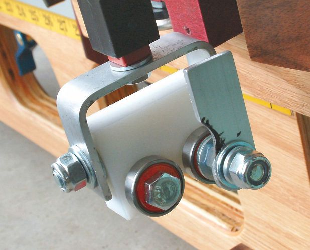
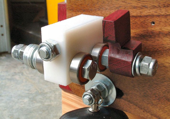
Install Aluminum yoke to toggle clamp. (Illustration) Do not tighten too much, just enough so handling it does not knock it loose. The reason this bolt must be a hex bolt is so you can tighten and loosen it while the bearing arm is in place -- with an open-end wrench.
-
Install front bearing arm to yoke
Toggle board
- Install toggle clamp assembly
- Attach toggle board to t-slot bolts and secure with star knobs
- By sliding the T-slot rail along the backer board set a beam
length so the front bearings are beyond the right edge of the backer
board. Clamp it in place.
- Complete final bearing arm counterbalance adjustments
Wrap Up
- Install handle on t-slot. Place it where it is fairly
well-balanced when the t-slot is in the position you normally use for
carrying the NF4.
- Apply beam length measuring tapes to the backer board. (Detailed instructions)
-
Determine and set fixed toggle bolt and position for toggle board. (Detailed instructions)
-
Align the three sets of bearings. (Detailed instructions)
- If you are building the NeuFinder 4.1 or later, prepare the digital scale and add it to the assembly. (Detailed instructions)
- Complete setup adjustments and calibration. (Detailed instructions)
- Install end caps to t-slot. If you have a 5/16" tap, you might
choose to thread the end hole in the t-slot to a depth of about 3/4".
You can get 5/16" bolts in this length. Bolts have a couple of
advantages over the plastic fasteners included with the end caps:
- They stay on when you want them to -- for instance, when you slide the beam as far as it can go.
- They can be removed when you want to -- for instance, to change the hardware.
Modification history:
- Nov 9, 2008 by DaveT - Reflect changes for NF4.1, using the UltraShip scale.