 Place
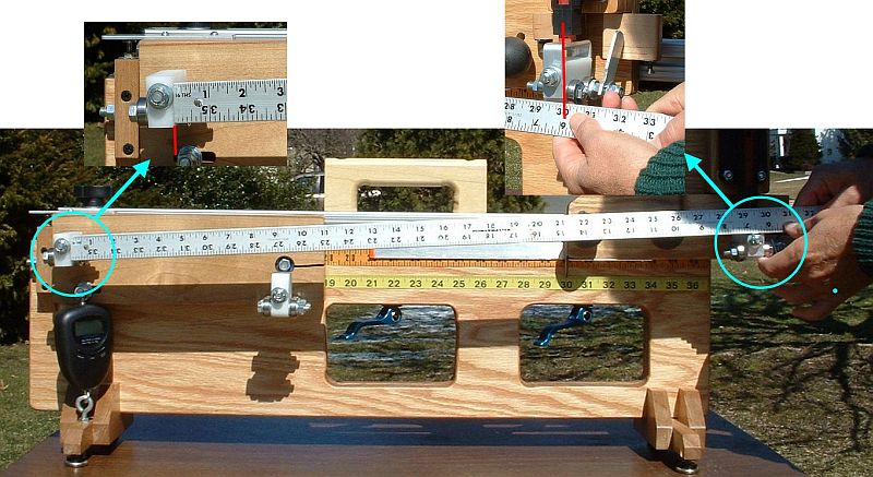
the end caps on the T-slot beam. Slide the beam all the way to the
left, so the cam-clamp's bolt is up against the beam's end cap, as
shown in the picture. Place
the end caps on the T-slot beam. Slide the beam all the way to the
left, so the cam-clamp's bolt is up against the beam's end cap, as
shown in the picture. |
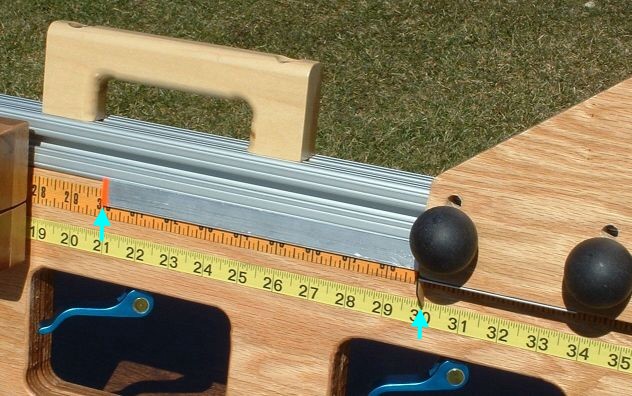
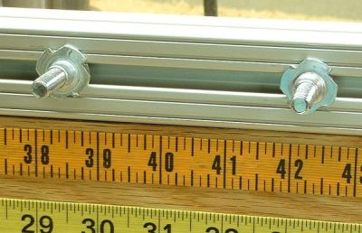
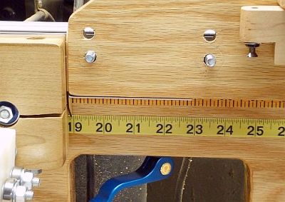 Slide the toggle board all the way to the left, so it is almost
touching the rotator board, as shown in the picture. The beam length in
this position should be 19" or a little less. If it is more than 19",
you have exceeded tolerances in placing a number of the holes you
drilled. Slide the toggle board all the way to the left, so it is almost
touching the rotator board, as shown in the picture. The beam length in
this position should be 19" or a little less. If it is more than 19",
you have exceeded tolerances in placing a number of the holes you
drilled. |
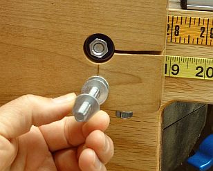
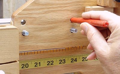 Mark this position on the beam using a marker or pencil through the middle of the unused pair of holes. Mark this position on the beam using a marker or pencil through the middle of the unused pair of holes.Release the cam clamps, and carefully slide the beam to the right until the "wand" is clear of the rotator board. While you do this, use your hand as a "clamp" to hold the toggle board in the same position relative to the beam. Carefully lift the toggle board off the bolts, being sure not to move the bolts in the beam slot. Actually, it is no disaster if the bolts move a little in the slot. Remember, you marked their position on the beam. Compare the bolts' position with the marks you made on the beam and, if necessary, slide the bolts in the slot so they line up with the marks. |
 Being
careful not to slide it along the beam slot, tighten one of the T-nuts
in place. You have now determined the location of the toggle board. Being
careful not to slide it along the beam slot, tighten one of the T-nuts
in place. You have now determined the location of the toggle board.The other T-nut should be just tight enough so the bolt tip does not wobble, but not so tight that the bolt cannot slide in the slot. That is because the clearance between the hole in the toggle board and the T-nut "bushing" is quite snug; it is tighter than the tolerance on the spacing between the holes. That means that there is no fixed position for the bolt that will work for both the upper and lower pair of holes. (If you have drilled the holes so accurately that it works for you, then you can tighten both T-nuts.) Hold the sliding bolt's T-nut in position with some sort of thread-locking compound. (Actually I used a bit of contact cement for the purpose. Worked fine, but it took over a day to set up properly.) |
 To start: To start:
|
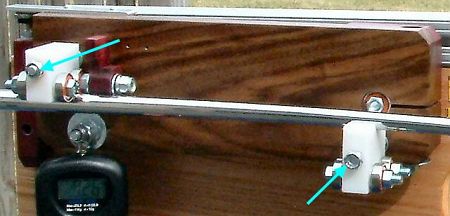
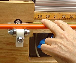
 You
will adjust the angle that the bearing sets point the shaft by
controlling each bearing arm's distance from the rotator board. Do this
by adding or removing the washers (see photo) between the bearing arm
and the rotator board. That's why you want the bearing arms held on by
nuts that you can spin off easily; you may be removing the bearing arms
several times during this procedure, to add or remove washers. You
will adjust the angle that the bearing sets point the shaft by
controlling each bearing arm's distance from the rotator board. Do this
by adding or removing the washers (see photo) between the bearing arm
and the rotator board. That's why you want the bearing arms held on by
nuts that you can spin off easily; you may be removing the bearing arms
several times during this procedure, to add or remove washers. |
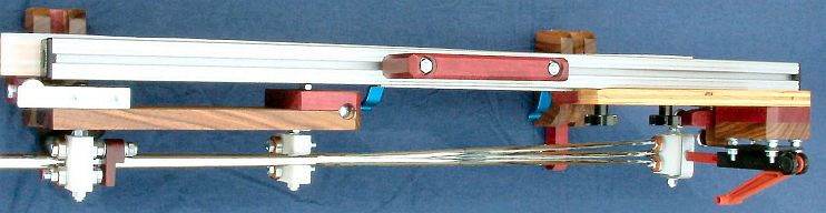
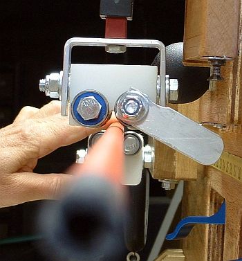 Place the toggle board in the upper (profiling) position. Set the beam length for 19". Place the toggle board in the upper (profiling) position. Set the beam length for 19".Find a fairly long (46" or so) wood shaft, that is as straight as possible. Any residual bend will jeopardize the accuracy of the results. As you go through the process, you will be able to judge how straight the shaft is. You may choose to switch shafts in the middle, to find a straighter one. That's OK; you will not have wasted much time doing the early work with a less-straight shaft. With the toggle clamp wide open and the tip stop out of the way, slide the shaft into the bearings from rear to front. Slide it in until the butt is within an inch or so of the rear bearings. There will be a lot of tip sticking out in front of the front bearings. The shaft should sit in the bearings of its own weight, since there is so much tip hanging out the front. Sight along the shaft from the front. It should look something like the photo. Ideally, the shaft will be centered between the bearings of the front bearing assembly. The alignment in the photo is pretty good, but the shaft is slightly to the right of center. |
 Place
your fingers in the position shown in the photo. Slide them crosswise
on the shaft to spin it in the bearings, while you continue to sight
along the shaft from the front. You will watch the tip move in a small
circle. The straighter the shaft, the smaller the circle, but I have
yet to see a shaft where the movement is invisible. Place
your fingers in the position shown in the photo. Slide them crosswise
on the shaft to spin it in the bearings, while you continue to sight
along the shaft from the front. You will watch the tip move in a small
circle. The straighter the shaft, the smaller the circle, but I have
yet to see a shaft where the movement is invisible.At the front bearings, the circle due to shaft bend will be a lot smaller than it is at the tip. But it may still be there. Estimate the middle of the circle by eye. That is the place that should be centered between the bearings. If the shaft is not centered between the front bearings, move the middle bearing assembly in or out by removing or adding washers. Find the washer combination that gives the best centering. If your washers are of different thicknesses, you can use that for a fine control of the position. But don't get paranoid about it. Being within 1/16" of center is really good. |
| When the shaft is pretty well centered, remove
it and set the beam length to 43". Insert the shaft again, and repeat
the test you did at 19". But this time, adjust the centering by adding
or removing washers from the rear bearings instead of the middle bearings. Once the shaft is well centered, check it again at 19". If it is within 1/16" of centered, you are done. Otherwise, fix it again at 19" (with the middle bearings) and again at 43" (with the rear bearings). At this point, it should be fine. |
Undo what you did in the first step:
|
 Now
the shaft alignment is whatever it is going to be. The next step is to
align the direction of the front bearing with the shaft tip. Now
the shaft alignment is whatever it is going to be. The next step is to
align the direction of the front bearing with the shaft tip.With the beam length at 43, insert the shaft and close the toggle clamp to bend the shaft. Rotate the shaft in the bearings (with your fingers as shown in the earlier photos), while you watch the bearings in the front bearing assembly. Each of the four bearings should turn in response to the turning of the shaft. If any of the bearings do not turn, the yoke needs alignment. Here's how to do it. Use an open-end wrench to slightly loosen the bolt that holds the aluminum yoke to the tip of the toggle clamp. Rotate the shaft while you turn the yoke. Find the position of the yoke where all four bearings turn, and tighten the bolt in that position. Check to make sure it is still in position after being tightened. |
| The bearing alignment is now complete. |