If
you...
|
You
should also...
|
Re-level the feet
|
Do nothing else;
this is
independent of other adjustments.
|
Re-mount the
rotator board
|
Review the
calibration. It
probably has not changed, but you should check.
|
Adjust the toggle
stops
|
Recalibrate.
|
Adjust the rotator
board angle
|
Recalibrate. |
Recalibrate
|
Before you
recalibrate, check --
and, if necessary, adjust -- the toggle stops.
|
Remove or replace
the toggle
clamp, yoke, or any part of the tip bearing assembly except the tip
stop or the bearings themselves
|
- If you changed the height of the tip bearings by more
than
1/16", adjust the rotator board angle.
- Adjust the toggle stops.
- Recalibrate.
|
Replace the meter,
or modify
anything about the meter mount
|
- Adjust the rotator board angle
- Check -- and, if necessary, adjust -- the toggle
stops.
- Recalibrate
|
Replace any of the
bearing
assemblies (not needed if replacing just the bearings themselves)
|
Adjust the rotator
board angle. |
Replace or modify
rotator board
|
- Mount the rotator board
- Adjust the rotator board angle
- Adjust the toggle stops.
- Recalibrate
|
Replace or modify
toggle board
|
- Adjust the rotator board angle
- Adjust the toggle stops.
- Recalibrate
|
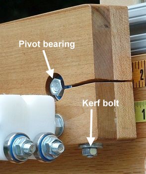 If
you haven't
already done so, slide the rotator board onto the pivot
bearing assembly. Start to tighten the kerf bolt, until you can just
slide the board in and out on the pivot bearings a fraction of an inch.
If you have already mounted the rotator board, then loosen the kerf
bolt, until you can just slide the board in and out on the pivot
bearings a fraction of an inch.
If
you haven't
already done so, slide the rotator board onto the pivot
bearing assembly. Start to tighten the kerf bolt, until you can just
slide the board in and out on the pivot bearings a fraction of an inch.
If you have already mounted the rotator board, then loosen the kerf
bolt, until you can just slide the board in and out on the pivot
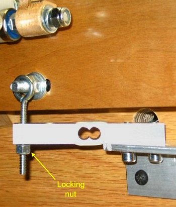
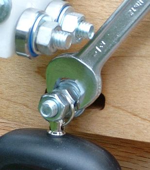
bearings a fraction of an inch.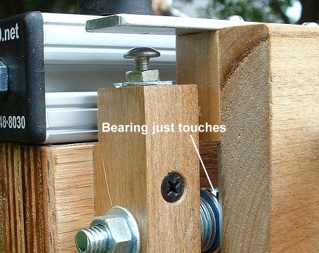 Slide the board in
or out, until the board just touches the stabilizer
bearing on the rotator stop (see picture). It is better that it just
miss touching it than that there is pressure between the bearing and
the rotator board. Pressure introduces friction, and makes the readings
less consistent.
Slide the board in
or out, until the board just touches the stabilizer
bearing on the rotator stop (see picture). It is better that it just
miss touching it than that there is pressure between the bearing and
the rotator board. Pressure introduces friction, and makes the readings
less consistent.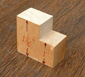 The
most reliable way to set the 15/8"
gap is to cut a small block of
hardwood with
exactly the right distance between the faces. Make the controlled
dimension be along the grain, so humidity has the minimum effect on it.
Trim it with a very
precise saw, and "sneak up" on the proper dimension. Check every trim
with precision calipers; I used a dial calipers good to .001". Aim at
being within .010" of the proper value.
The
most reliable way to set the 15/8"
gap is to cut a small block of
hardwood with
exactly the right distance between the faces. Make the controlled
dimension be along the grain, so humidity has the minimum effect on it.
Trim it with a very
precise saw, and "sneak up" on the proper dimension. Check every trim
with precision calipers; I used a dial calipers good to .001". Aim at
being within .010" of the proper value.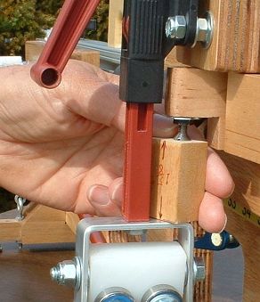
 Set the toggle board
in the profiling position (with the bolts through
the lower set of holes).
Set the toggle board
in the profiling position (with the bolts through
the lower set of holes).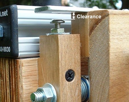 Retract
the rotator
board stop screw. Set it to a large clearance, to allow the
maximum rotation of the rotator board.
Retract
the rotator
board stop screw. Set it to a large clearance, to allow the
maximum rotation of the rotator board.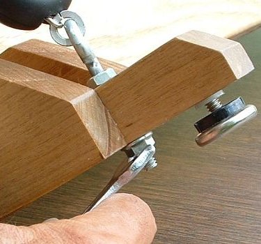
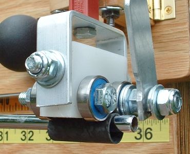 A
more general
solution is to use a hard tubular sleeve to measure such shafts. Place
it over the tip, as shown in the
picture. The thickness of the sleeve wall should take out some or all
of the slack in the measurement. One of the best sources for a sleeve
is a few inches cut from
the butt of a graphite shaft. The next time you butt-trim about three
inches from a graphite
shaft, save the trimming for this purpose. It fattens the tip
for measurement purposes, enough to add about 0.20Kg to the reading,
which is enough for most shafts. If the sleeve is not thick enough for
all your
shafts (which is possible), you can cut a sleeve from a section from
thicker-wall
aluminum tubing or hard plastic pipe.
A
more general
solution is to use a hard tubular sleeve to measure such shafts. Place
it over the tip, as shown in the
picture. The thickness of the sleeve wall should take out some or all
of the slack in the measurement. One of the best sources for a sleeve
is a few inches cut from
the butt of a graphite shaft. The next time you butt-trim about three
inches from a graphite
shaft, save the trimming for this purpose. It fattens the tip
for measurement purposes, enough to add about 0.20Kg to the reading,
which is enough for most shafts. If the sleeve is not thick enough for
all your
shafts (which is possible), you can cut a sleeve from a section from
thicker-wall
aluminum tubing or hard plastic pipe.
 Put the toggle
board in the matching position (the T-slot bolts go through the upper
holes in the toggle board).
Put the toggle
board in the matching position (the T-slot bolts go through the upper
holes in the toggle board).