Spine-Finding 2

Dave Tutelman -- January 11, 2006

Differential Deflection

OK, you know how to do feel-finding, but that doesn't give a true reading of the spine. You know how to find FLO, but you have an NF4 and not a frequency meter. How do you get a true picture of the stiffness variation around the shaft?

The answer is to measure the stiffness with the NF4 in each orientation of the shaft. The NF4 measures stiffness by "differential deflection'; it starts from a partially deflected (pre-loaded) shaft, and measures the load produced by a known difference in deflection. The pre-load gets rid of any of the geometric effects that disrupt a feel-finder. In other words, residual bend does not affect an NF4 measurement.

A Procedure for DD Spine-Finding

1. As with feel-finding, set the beam length for the section of shaft you want to spine. The most natural thing is to use the same beam length you do for matching shafts.

2. As with feel-finding, secure the toggle board in its lower position, for maximum throw of the toggle.
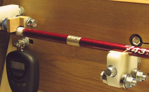
3. Place the shaft in the bearings, with the tip against the tip stop. Unlike feel-finding, you will turn the middle bearing to the V-groove side. If you have a UHMW bearing block, you may need masking tape in the groove to keep the shaft from slipping. (In the photo, the shaft is resting on masking tape in the V-groove.)

Note: Just because the shaft does not look like it is slipping does not mean it isn't. This procedure depends on very precise readings. When I started doing it, I was getting flaky readings until I added the masking tape. When I carefully repeated the process without the masking tape, I was able to measure the shaft rotating a few degrees under load, that I would never have noticed naked-eye.


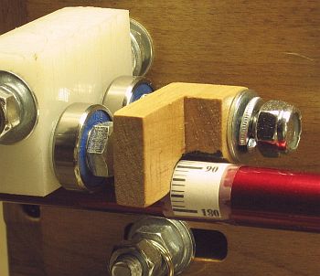
4. You may have noticed that, instead of masking tape under the marking guide, there is a what looks like a label imprinted with an angle "ruler". Here is a closer look at it. It is fixed to the shaft with clear tape, and shows angles from 0º to 180º.

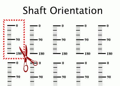
The label is cut from a sheet of such labels, shown above left. The picture of the sheet above is a link that you can use to download the whole sheet as a printable PDF file. Having downloaded it, print it at exact size and cut it apart for labels. In order to test for exact size, measure the distance from the middle of the 0º hash mark to the middle of the 180º hash mark. It should be just barely less than 23.9 millimeters.

5. Having printed and cut your label, affix it to the shaft under the marking guide. The combination of marking guide and label will tell you the exact rotational position of the shaft in the NF4. A few things to remember:
  • The beam length should be long enough so the label is on the parallel section of the butt of the shaft. If it is further down, on the tapered portion of the shaft, the angle markings will not be accurate. You can still use it to find and note the spine and NBP, but you can't depend on the label markings to give you the angle between them.
  • You only need 180º of measurements because physics says the other 180º will be symmetrical. Experiments by John Kaufman and myself have verified this. Those experiments include Type 1 and Type 2 shafts, shafts with large spines and those with almost none.
  • Therefore, you should put the label on the side of the shaft you intend to use as the marked side when you assemble the club. (This matters, for instance, if you care whether the label is up or down.)
7. Measure the 19 positions from 0º to 180º. Start by turning on the digital scale and preloading the shaft with the L-shaped stop. Then, at each position:
  1. Set the shaft in position against the tip stop and at the correct angle. Use the same motion and pressure every reading. My technique is to slide the shaft about a quarter inch away from the tip stop, then back to the stop, then rotate to the next angle to be measured.
  2. Recheck that the toggle is firmly pre-loaded, and tare the scale.
  3. Toggle to full load and read the scale. Record the reading.
  4. Tare, and return the toggle to pre-load. Read the scale. It should be the negative of the former reading within .02Kg. If so, return to step A for the next position of the shaft. If not...
  5. Discard the reading that you recorded. Go back to step B and continue from there.

Compare the reading at 0º to the reading at 180º. If they differ by more than 0.02Kg, something has changed during your execution of step #7. The most likely thing to have changed is your technique for seating the shaft at the new angle, or the shaft slipping rotationally. (Did you use masking tape in the V-groove?) If you get a 0.02Kg or more discrepancy, you probably want to repeat step#7, at least until you see your readings tracking those of your first run.

At this point, you have 19 readings associated with positions around half the shaft. Let's turn those readings into spine and NBP.

Interpreting the data

Here's an example of data taken from a shaft with a hefty spine. It is a several-years-old AJ Tech shaft (model Z-43, R-flex); at the time, AJ was known for shafts with a lot of spine.


10º
20º 30º 40º 50º 60º 70º 80º 90º 100º 110º 120º 130º 140º 150º 160º 170º 180º
2.81
2.78
2.73
2.71
2.69
2.71
2.73
2.79
2.82
2.92
2.93
2.98
2.99
3.02
3.00
2.96
2.92
2.86
2.79
 
We can easily see the lowest reading (2.69Kg @ 40º, in blue) and the highest (3.02Kg @ 130º, in red). The conclusions we draw are:
The shaft is a well-behaved "Type 2" shaft; that is, feel-finding provides very similar information. Feel-finding gave an NBP at 30º and a spine at 130º. Not exactly the same, but close.

So which is correct? Well, we can tell by FLO, because FLO gets at the real problem: any out-of-plane force will cause the shaft to wobble. I ran a FLO test, and here is what I found:

Angle
Event
Result of
FLO test
30º Feel-finding NBP
Some wobble
40º Diff Defl NBP
FLO
130º Feel-finding spine
and
Diff Defl spine
FLO
90º Not near anything
Serious wobble

My conclusion is that differential deflection gave a more accurate location of the NBP and just as accurate a location of the spine as did feel-finding.

This example was good for a tutorial, because the shaft was an ideal case for spine-finding using differential deflection. Not all shafts will be, so let's look as some more examples.

Another example: More typical graphite shaft

The first example showed a pretty ideal case: a big enough spine so that careful measurement will show the spine and NBP unambiguously.

But most shafts are not like that. In particular, most shafts don't have nearly that much spine. In such cases, it might be harder to locate the spine and NBP by differential deflection. Why? Remember that the resolution of the NF4 is 0.01Kg, and the precision is probably not better than 0.02Kg. And you have to be careful in your technique and take additional check readings to get 0.02Kg. But most spines are less than the 0.33Kg we saw in the first example. When the spine is the same order of magnitude as the precision of the instrument, it is a lot harder to see the peaks and valleys.

Consider the next example, a True Temper EI-70 R-flex shaft. It has a lot less spine: a total difference of only 0.07Kg. Here's the data from that shaft.


10º
20º 30º 40º 50º 60º 70º 80º 90º 100º 110º 120º 130º 140º 150º 160º 170º 180º
3.64
3.63
3.63
3.60
3.60
3.61
3.61
3.62
3.61
3.62
3.63
3.63
3.64
3.66
3.67
3.66
3.66
3.65
3.66

Just looking at the raw data, it looks like:
That doesn't look too far off. There's 105º between spine and NBP, which isn't 90º -- so it can't be exactly right. But it doesn't look too crazy.

But now let's think about the precision of our measurements. Note that there's a little "back and forth" away from the spine and NBP. For instance, there are sequences of 3.62-3.61-3.62 and also 3.66-3.65-3.66 that are not part of the principal directions. That brings us back to reality; our measurements are not exact. Recalling that our precision is probably no better than 0.02Kg, let's look at the data again. This time, let's consider a run of data within 0.01Kg of the maximum or minimum to be a candidate, even accepting data during that run that might exceed 0.01Kg. For instance
 Here's what the data looks like now.


10º
20º 30º 40º 50º 60º 70º 80º 90º 100º 110º 120º 130º 140º 150º 160º 170º 180º
3.64
3.63
3.63
3.60
3.60
3.61
3.61
3.62
3.61
3.62
3.63
3.63
3.64
3.66
3.67
3.66
3.66
3.65
3.66

This new interpretation of the data is:
I used these as starting places to look for FLO, and found:
This makes a lot of sense. The spine and NBP are not far off our estimates (once we allowed for limited precision). The spine and NBP are 90º apart, as they should be. And the spine is not a big one; it's just under 3cpm, which is about where many clubmakers wouldn't put stock in spine orientation making a difference.

Before we leave this example, let's look again at the relation between feel-finding and differential deflection. Feel-finding this shaft turned up an NBP at 70º, a smaller NBP at 200º, and only one detectable spine at 310º.

Angle
Event
Result of
FLO test
55º Diff Defl NBP
FLO
70º Feel-finding NBP
Slight wobble
145º
FLO
155º Diff Defl spine
Very slight wobble
200º Feel-finding
secondary NBP
Wobble
310º Feel-finding spine
(only one)
Slight wobble

So feel-finding gave results that were only somewhat related to FLO. Since FLO is the most precise indicator of directional stiffness, we have to conclude that feel-finding is less effective than differential deflection. Feel finding may give results with a higher resolution and certainty, but with less relation to reality than differential deflection provides -- based on a FLO check.

Another example: Cheap graphite shaft

"Inexpensive" does not necessarily mean "cheap". But in this case, it does. I took a house brand shaft (Select Gear from Hireko, made by Aldila), and put it through our tests. It had a significant spine (about 7cpm). That is certainly big enough for most clubmakers to want to either align it or discard it, but not the overwhelming spine of our first example. Feel-finding gave an NBP at 330º, a small secondary NBP at 200º, and only one detectable spine at 90º.

Let's look at the Differential deflection measurements.


10º
20º 30º 40º 50º 60º 70º 80º 90º 100º 110º 120º 130º 140º 150º 160º 170º 180º
2.65
2.67
2.69
2.72
2.74
2.77
2.78
2.81
2.81
2.80
2.79
2.76
2.74
2.73
2.69
2.67
2.67
2.65
2.64

Again, we are highlighting the areas of low and high readings to a 0.01Kg precision. We infer from the data that:
The FLO test shows that we are close. We get FLO at 80º and 170º. Here are the detailed results.

Angle
Event
Result of
FLO test
80º Diff Defl spine FLO
90º Feel-finding spine
(only one)
Very slight wobble
170º
FLO
175º Diff Defl NBP
Very slight wobble
200º Feel-finding
secondary NBP
Wobble
330º Feel-finding NBP
Wobble

Once again, feel finding misleads us about where the true spine and NBP are located, while differential deflection comes very close. And once again, the planes of FLO are 90º apart, as physics says they should be.

Another example: Type 1 steel shaft

Finally, let's show the data for the Type 1 steel shaft that was mentioned in the section on Feel Finding.


10º
20º 30º 40º 50º 60º 70º 80º 90º 100º 110º 120º 130º 140º 150º 160º 170º 180º
4.81
4.79
4.79
4.79
4.80
4.79
4.79
4.82
4.82
4.82
4.81
4.81
4.80
4.81
4.81
4.80
4.81
4.81
4.82

The entire set of measurements are compressed into a 0.03Kg range, suggesting that we can ignore spine considerations.  The size of the spine in the frequency domain is less than 1cpm. And the shaft FLO'd in any orientation we clamped it, further confirming that the spine was negligible.

Once again, this information is clear in looking at the differential deflection measurements. But feel-finding showed a strong NBP and spine, suggesting that orientation of this shaft would be important. In fact, of all the shafts tested, feel-finding was most dramatic here in saying that this shaft should be aligned -- judged on how hard it was to turn the shaft away from the NBP or keep it on the spine. And, in fact, this was the shaft that had the least need for spine alignment.


Last modified by DaveT - 1/13/2006