Shaft Marking Guide

Dan Neubecker & Dave Tutelman -- March 24, 2005

The shaft marking guide is used to mark the orientation (rotation) of the shaft in the bearings, particularly for marking the direction of the spine or NBP. The marking guide in prior models of the NeuFinder were mounted to the rotator board. This presented a problem, in that any change or variation in the distance from the rotator board to the shaft 
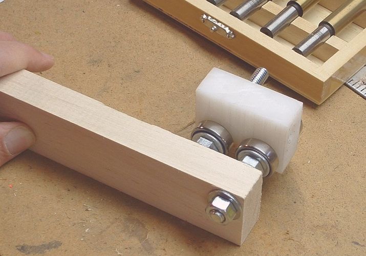
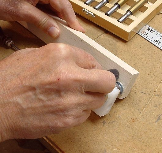
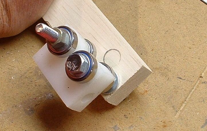
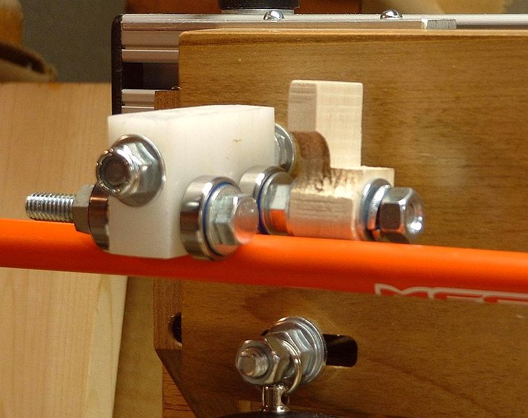
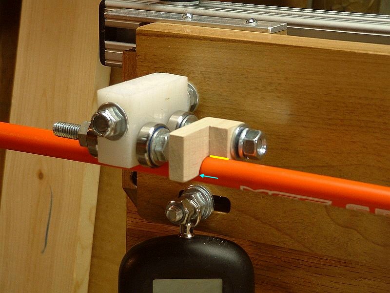
introduced a potential error in marking the top center of the shaft.

In the NF4, the marking guide is mounted on the rear bearing assembly, so its relation to the shaft is fixed. Here are a couple of pictures how that works. In the one on the left, the marking guide is open, away from the shaft. On the right, it is ready for business. In that picture, the edge highlighted in yellow is the guide for marking the top center. Another edge, pointed to by the blue arrow, can be used for a mark 90 degrees away.
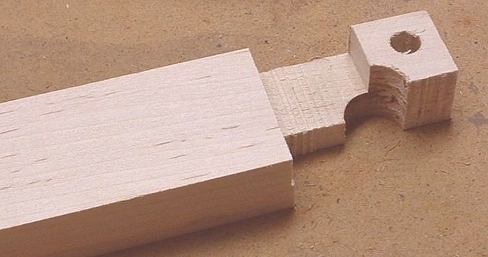
The shaft-marking guide is a unique part that must be fashioned to fit the individual NF4 it is being built for.  The reason for that is because it is placed over the inside bearing bolt in your rear bearing arm and must rotate down over an installed shaft during use and therefore require very tight tolerances.  Because the bearing arms are hard to make that precisely, the marking guide must be custom-fit 
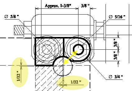
to the rear bearing assembly on which it will be mounted. The critical dimensions are highlighted in yellow on the excerpt from the plans at
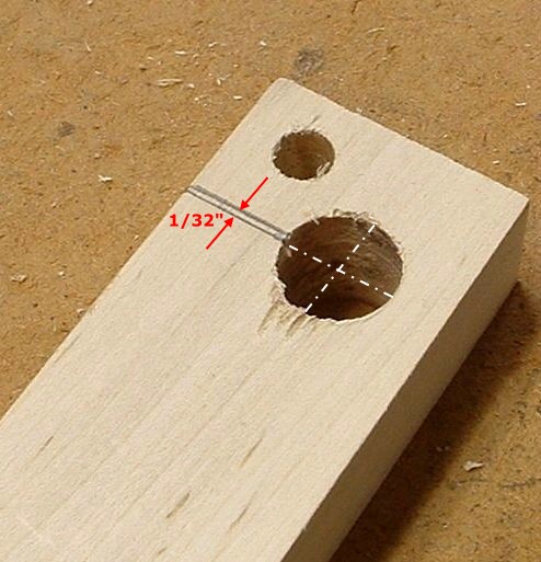
 the right. They are:
  • The exact spacing and direction between the bearing bolt hole and the hole for the shaft.
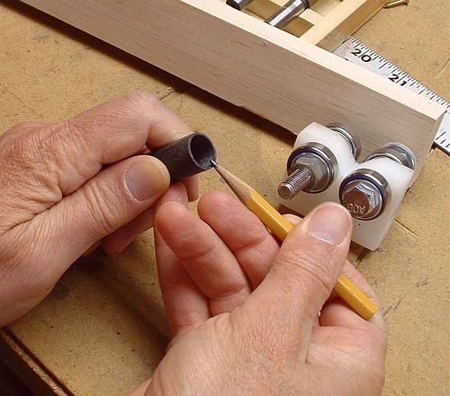
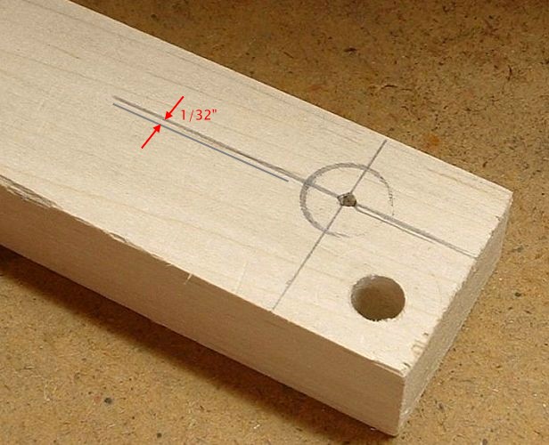
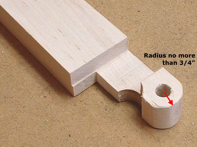
  • The positions of the edges used for marking (of course), which are offset 1/32" from the centerlines of the shaft hole. This is to make room for the width of a marker tip.
These are the dimensions that must be fit to the specific NF4. Below is a procedure to get it right.

I have made two of them, one for my prototype and one for my beta unit.  One was made out of the same UHMW poly material that the bearing arms were made from and the other was made out of hardwood.  Both work fine.  If I were doing another, I would probably make it from the UHMW material, since I found it a little easier to work with.

Drilling the holes

Start with a piece of material 3/4" thick and about 1-1/2" wide. If you are using hardwood, this is exactly the size of a standard "1-by-2". It should be long enough to have a good "handle". I prefer at least 4" of length, but I use a radial arm saw and need more safety margin that a table saw would.

For the rest of this description, we will call this piece the "guide board". At the very end, it will actually become a marking guide.

Drill a 5/16" hole through the material, centered 3/8" from the end and 3/8" from the edge, as shown in the picture.
Take the rear bearing assembly off its mounting bolt. Once you go through this process, you will have a marking guide for this side of this bearing assembly. It won't necessarily work for any other bearing assembly or even this one if turned around. So leave the assembly intact on the bearing arm. You know which side is which because the bolts are different lengths. The 3" (longer) bolt is the mount for the marking guide.

Put the 3" bolt through the hole you just drilled, as shown in the photo. Protect each side of the guide board with a washer, and attach it with a nut. Get the top edge of the bearing arm perfectly parallel to the top edge of the guide board. (A bubble level can help with that.) Tighten the nut in this position, so the guide board is rigidly held to the bearing arm in the parallel position.

You thought you were going to use your NF4 to tell you where to trim shafts. Little did you know you would first have to use a shaft to tell you where to trim the NF4.

Take a section of shaft trimmed from the butt. You'll need about 3", which you probably have around your shop somewhere. Ideally, it should have an end that is cut perfectly square. Put some sort of marking medium on the square end. In the picture, I am scrubbing the side of a pencil on the end, to get it coated with black graphite powder. (A little wet paint also works, as does stamp-pad ink. You'll find something.) Now the shaft end is a "stamp", in the form of a circle.

Hold the shaft section firmly in the bearings, and press the stamping end against the guide board. Being careful to keep the shaft firmly in the bearings and the bearing arm parallel to the guide board, rotate the shaft in the bearings while pressing it against the board. It should leave a nice circular mark on the guide board, at exactly the position a shaft would intersect the guide if the shaft were being measured in the NF4.

On the right, you see what the circular mark will look like if you do it reasonably well.

Find the precise center of the shaft circle, and mark it with a center punch. Draw a centerline through it, parallel to the edge of the guide board. Draw another line parallel to the first and 1/32" away from it, as shown in the photo. We will use this second line later.
Drill a 5/8" hole for the shaft.

To test whether you did it right, you can bolt the guide board to the bearing assembly again. The shaft section should go right through the hole.

Critical edges

Turn the guide board over, and draw a centerline of the shaft hole, perpendicular to the edge of the board. Draw another line, parallel to the first and 1/32" closer to the bolt hole.
Starting precisely at the last line you drew, remove material to a depth of 3/8". Keep removing material until the groove you are cutting is almost 2" from the end of the guide board.
Remember that line we drew earlier? The one that was parallel to the centerline and parallel to the edge of the board. Now we're going to use it.

Turn the work 90 degrees, so the board is on edge. Set your saw's depth to remove material exactly to that line. Now remove that material, so the guide board looks as it does in this photo.

Finishing the job

You've heard the joke about the sculptor where the punch line is, "Now remove everything that doesn't look like an elephant." Well, that's where you are now.

Remove everything that doesn't look like a marking guide, as described by the plans and this photo. The only critical part here is to assure that the rounded edge has a radius of no more than 3/4". If it's larger than that, it might touch the shaft when the marking guide is open.
Cut the shaped marking guide from the guide board at the proper length. (The length is not at all critical.)

Sand and finish the marking guide, then mount it on the bearing assembly.