Bearing Arms

Dan Neubecker with Dave Tutelman -- March 19, 2005

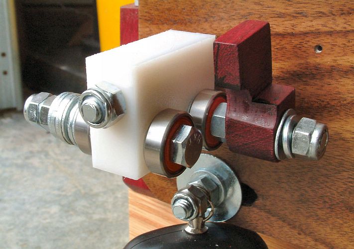
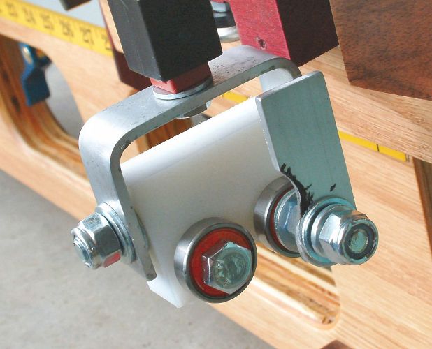
There are three bearing arms to be made. All three are seen in use in the photo.

The front and rear bearing arms are identical, though there is a slight difference in the hardware we hand on them.  The middle bearing arm is identical on the side where the bearings are, but is deeper and includes a V-notch on the other side.

When a shaft is measured in the NF4, it is deflected (bent) by force applied at the bearing arms. In the photo, the shaft sits the front and rear bearings, and in the V-notch of the middle bearing arm. It is oriented this way for some types of measurements; for others, the middle bearing arm is flipped and the shaft sits in the bearings rather than the V-notch.

Drilling

Start by cutting the three rectangular pieces out of your ¾” UHMW stock.  Next, drill the three 5/16” holes though each block.

The location of the holes and drilling must be precise, because if they are not, the bearings will not set evenly and not all will contact the shaft at the same time, reducing their effectiveness at sharing the load.

To do this accurately, I suggest making a jig from a few scrap pieces of wood that you can clamp down to your drill press.  This jig would have a wood base piece, and two vertical pieces of wood set at 90º to each other and to the base.

Once you get this jig positioned properly in your drill press, you can drill all three holes by placing the piece into the L-shape formed by the upright pieces, drilling, rotating the piece, drilling, and turning it up on end and drilling.  Using a jig like this ensures that the holes you drill are all exactly the same distance from the edge of the stock, which is a key to getting even bearings.

 The middle bearing arm will require a different setup of the jig for the end-to-end hole, but otherwise, once it is setup, you can drill all the other 5/16” holes without moving it.


Shaping

Next you need to cut the notches in the bearing blocks.  There is a notch needed between the bearing bolt holes on the front and rear bearing arms and one needed on both sides of the middle bearing arm.

I cut these all on a router table with a 45º v-shaped bit, set to the depth indicated in the plans.  I set the table up so that the V was cut as close to the center as possible.  To unsure that I had an even cut on both sides, I ran it through one way, turned it 180º and ran it through again.  This way, if I were slightly off center with my first cut, the second cut would even both sides out.
Once the Vs are cut, those Vs that are between the two bearings bolts need to have the sharp corners rounded off.  This is necessary to ensure that a shaft can never come in contact with the bearing arm itself rather than just the bearing.  You should end up with a v-shape with rounded legs.  However, the v-notch on the other side of the middle bearing arm should not be rounded, since the shaft will come into direct contact with this when you use it.

Any other rounded corners, etc. shown on the plans are optional and really only shown for aesthetic reasons.

Subassembly

The bearing arms are now ready for subassembly. Put the bearing assemblies together according to the component assemblies document. The photos below show some of the assembly detail.


Rear bearing assembly
You will not be able to mount the shaft marking guide until you have finished making it, which comes later.

Middle bearing assembly

Front bearing assembly
Fabricate the tip stop from a short piece of 1/8" aluminum strip, as shown in the plans.