Toggle Board

Dan Neubecker & Dave Tutelman -- March 19, 2005

Before you begin the toggle board, familiarize yourself with how it all fits together.


Front view of wood pieces,
including the toggle support assembly.

Rear view of wood pieces.
(Please ignore the counterbores in the four ¼" holes. They represent a prior version of the plans; the final plans do not counterbore those holes.)

Finished toggle board

Another view of the finished board, including some terminology.

There are two indicators on the toggle board for measuring the beam length.
  • An aluminum extension "wand", for reading the upper scale.
  • A "cursor" made of a section of tongue depressor or popsicle stick, for reading the lower scale.

The toggle board is mounted on the sliding aluminum beam by a pair of bolts, which are held on the beam by T-nuts. The toggle board slides on over the sleeves of the T-nuts.

Initial cutting and drilling

Begin by cutting the hardwood plywood back piece to its suggested rectangular size.

Also cut the rectangular, vertical support pieces out of hardwood or hardwood plywood, If you use hardwood, the grain should run lengthwise.
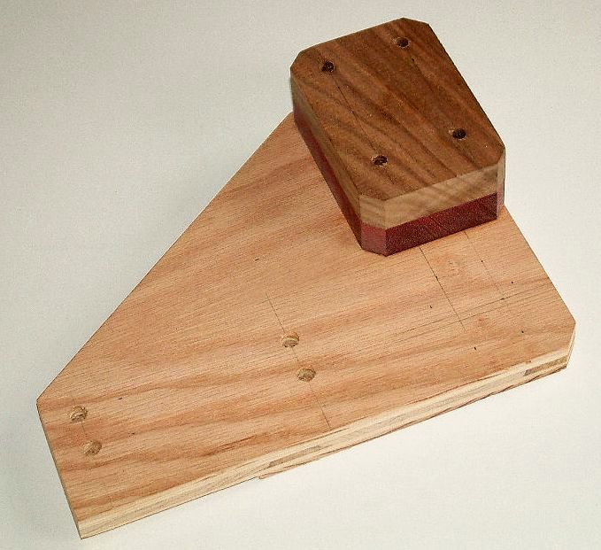
Cut the slot in the back, lower left of the main toggle board piece, the slot for the aluminum beam-length measuring extension.  This slot can be cut with a table saw and the piece held vertically, or with a router.  It is ok if the cut runs a little longer or wider than the plans call for, as it would be in the event of using a table saw.

On the front of the main toggle board, very carefully measure and mark the location of:
  • The four 3/8”holes.
  • One of the 1/4" holes, the lower left one, as viewed from the front of the board.
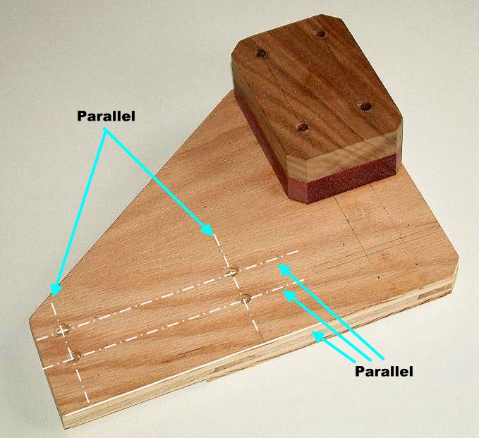
The position of the 3/8" holes is very critical to proper operation. In particular:
  • The lower pair of holes must share a centerline that is exactly parallel to the lower edge of the board.
  • Slightly less critical, but the same is true of the upper pair of holes.
  • The centerlines shared by the right and the left pair of holes must be parallel.
These three criteria are shown in the photo.
Create starter holes for drilling at each of these marks.

Next, clamp the toggle board down to your drill press table so that you drill is as accurately aligned as possible and the holes are drilled perpendicular to the surface.  Use a very small bit, maybe 1/16” or 3/32”; it should be smaller than the pilot point of the bits you will use to drill and to counterbore the holes. Drill completely through the piece, from the front, at each location.

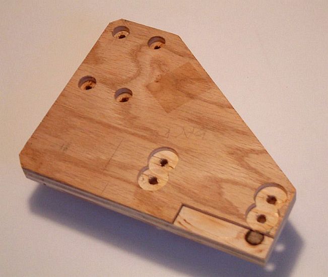
On the back of the toggle board, there should now be 5 small holes showing. On the four holes that will eventually be drilled to 3/8", proceed to drill the counterbores to the size and depth indicated in the plans at each location, using the small pilot holes as a guide to position the bit.

From the front of the board, use the same small pilot holes to the drilling of the full size holes. Drill all five, but note that one of them must be only 1/4".

Note that the plans ask you to drill the 3/8" holes to a starting diameter of 3/8”, but that they may need to be adjusted to fit the outside diameter of your t-nuts.  They should end up in the range of 3/8”, 25/64” or 13/32”, based on what the beta builders experienced.  You want a fairly snug fit, not a loose and sloppy fit.

The 3/8" holes also have a small countersink inside the counterbore at the back edge of the hole.  Those should be drilled next.
 
With the holes drilled and notches cut, you should cut the angle on the back piece of the toggle board.  First draw the location of the angle on the front of the piece.  On my table saw, it turned out that the cut angle was just under 36º on the miter guide (35.8º, calculated in the plans).  You might make your first cut can cut away from the line a little bit to visually confirm that your angle setting is correct before you make the final cut.

Now would be a good time to round or chamfer the edges of the support pieces, if you plan to do so.

Toggle support assembly

Glue and clamp the support pieces in place, over top of the ¼” hole.

When the glue has dried, turn the toggle board over so that the back is facing up. Clamp and support it on the drill press table so you can be absolutely sure you are drilling perpendicular to the surface.  Use the ¼” hole you drilled through the back piece as a guide, drill the holes through to the front side of the support pieces.
Insert a carriage bolt through the ¼” hole from back to front, and place the toggle clamp on the bolt in the position it will eventually take when assembled. Run a nut onto the bolt, holding the toggle clamp lightly in place.

Using any measurement equipment you feel will be constructive, align the toggle clamp so its action is perfectly perpendicular to the bottom edge of the toggle board. If you aligned the support blocks really well when you glued them on, they will be a very good guide. Just align the toggle clamp's edges parallel to those of the support block.

When the toggle clamp is perfectly aligned, tighten down the nut to hold it in place. Check to make sure it is still perfectly aligned.

Mark on the support block the centers of the three empty mounting holes in the toggle clamp's base. Be careful not to disturb the alignment of the toggle clamp as you do this.

Now remove the nut, toggle clamp, and carriage bolt. Drill the remaining three holes through the assembly.

Beam-length measurement indicators

Install the beam length extension "wand" to the back of the toggle board, in the slot/notch that has you prepared for it. The important positioning cues are:
  • It should be installed so that exactly 10” of the aluminum marker sticks out from the left edge of the toggle board.
  • It should be perfectly parallel to the bottom edge of the toggle board.

Begin by drilling the mounting holes in the aluminum strip, and countersinking them for the flat-head wood screws. The countersinking must be sufficient so the screws are recessed below the level of the aluminum and cannot scratch the backer board or measuring tapes. Deburr the holes.

Find a perfectly flat tabletop. On it (or on a large piece of cardboard or hardboard on the tabletop) rule two parallel lines exactly 10" apart.

Apply contact cement to the aluminum strip where it meets the slot on the back of the toggle board, and to the slot as well. When it is tacky, place both pieces on edge on the tabletop, with the tip of the aluminum on one line and the tip of the toggle board on the other line. (See diagram) Bring the tacky surfaces together in this position. That way, the bottom of the toggle board and the bottom of the aluminum strip will be in exactly the same plane, and the extended wand will be exactly 10" long.

Secure the aluminum to the backer board with the flat-head wood screws.

Shape the beam length "cursor" from a tongue depressor or popsicle stick, and glue it in position at the edge of the toggle board.


A request....

You will note that we do not have photographs of some important steps in this section. If you are making an NF4 and are handy with a digital camera, please take the photos you would have liked to see in this chapter and send us copies. We will add them to the instructions.

Thank you!