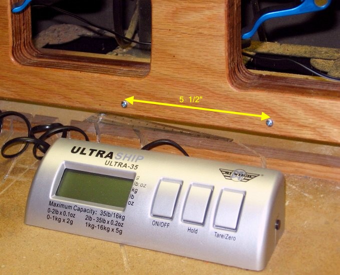
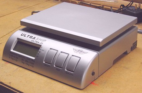
 Here is the MyWeigh UltraShip
35 scale, as it comes out of the box. It has buttons for "on/off",
"tare/zero", and "hold reading". The black button on the side selects
the units; for the NF4, we use kilograms.
Here is the MyWeigh UltraShip
35 scale, as it comes out of the box. It has buttons for "on/off",
"tare/zero", and "hold reading". The black button on the side selects
the units; for the NF4, we use kilograms.The scale comes in silver or black. This one is silver. Pick the color you like; it doesn't matter to the operation of the NF4.
I recommend testing the scale before you continue. Here is a link for testing digital scales.
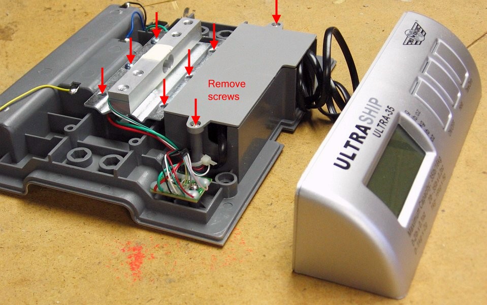
 Begin the disassembly of the
scale by removing the plastic top tray. It is press-fit on, and can be
pried off by hand.
Begin the disassembly of the
scale by removing the plastic top tray. It is press-fit on, and can be
pried off by hand.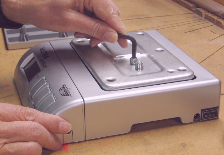 Remove
the metal plate. This requires removing two hex socket machine screws.
While the screws are a metric size (6mm-1mm), they can
be removed using a 3/16" Allen wrench.
Remove
the metal plate. This requires removing two hex socket machine screws.
While the screws are a metric size (6mm-1mm), they can
be removed using a 3/16" Allen wrench.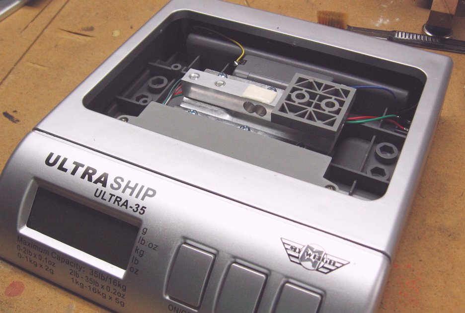 This is what
the innards of the scale looks like.
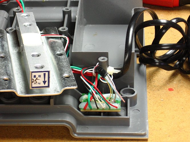
This is what
the innards of the scale looks like.The metal beam with the gray plastic pad resting on one end of it is the "load cell" for the scale. The beam has a pair of strain gauges, one on the top of the beam and the other on the bottom. Each strain gauge is encapsulated under a white resin for protection. When the beam is flexed, the strain gauges record the tension on one side and compression on the other side. This difference is converted by the electronics into a weight.
All the electronics is in the display unit at the front of the scale. That unit is removable, remaining attached to the rest of the scale by a coiled wire.
 Unscrew
the bottom of the scale. The four screws are hidden under four adhesive
"feet" that you must peel off.
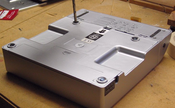
Unscrew
the bottom of the scale. The four screws are hidden under four adhesive
"feet" that you must peel off.Save all the screws, bolts, and washers you remove from the scale. You will use several of them before the installation is complete.
 Remove
the electronics
(attached to the bottom of the scale) from the case. No need to do any
fancy prying; start it by just putting your fingers underneath and
pushing up.
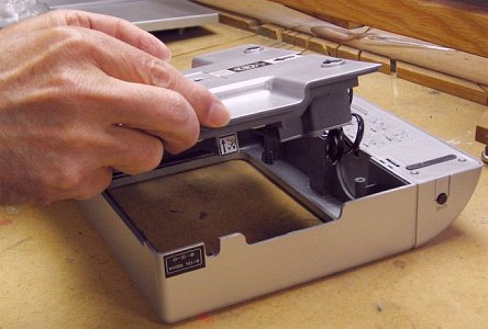
Remove
the electronics
(attached to the bottom of the scale) from the case. No need to do any
fancy prying; start it by just putting your fingers underneath and
pushing up.Then detach the display/control unit from the case. It was designed to slide off, per the instructions on the bottom of the unit. In case you have trouble with the instructions (they are printed very small), with the scale still upside down, just push the latch tab forward and push the display/control unit down until it slides off the main unit.
 You now
have the main unit (sans cover) and the display/control unit.
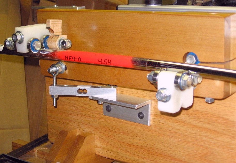
You now
have the main unit (sans cover) and the display/control unit.Measure the load cell beam. It should be 100mm long (about 4"), with threaded holes at 6mm and 24mm from each end. If it is significantly different from this, do not continue. Instead, notify us. It would indicate that MyWeigh has changed the design enough that we need to evaluate whether our design is still functional.
If all is still "go", remove the screws indicated in the picture.
 The
key pieces in this picture are the load cell and a tiny connector board
for all the wires in the main unit.
The
key pieces in this picture are the load cell and a tiny connector board
for all the wires in the main unit.Look at the load cell beam. It should have an arrow at the unsecured end, as shown in the photos. (By "unsecured", I mean the end not screwed to the steel plate.) The arrow should point toward the steel plate. If your load cell does not have an arrow, then take a waterproof marker and draw one. It should be at the unsecured end, and point toward the steel plate, as the picture shows.
Look at the wires coming off the connector board. Slide the wires and cable tie off the plastic post.
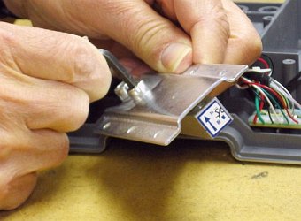 Remove the load cell beam
from its steel plate mounting. Unscrew the screws with the 3/16" Allen
wrench.
Remove the load cell beam
from its steel plate mounting. Unscrew the screws with the 3/16" Allen
wrench.Unscrew the connector board from the gray plastic base.
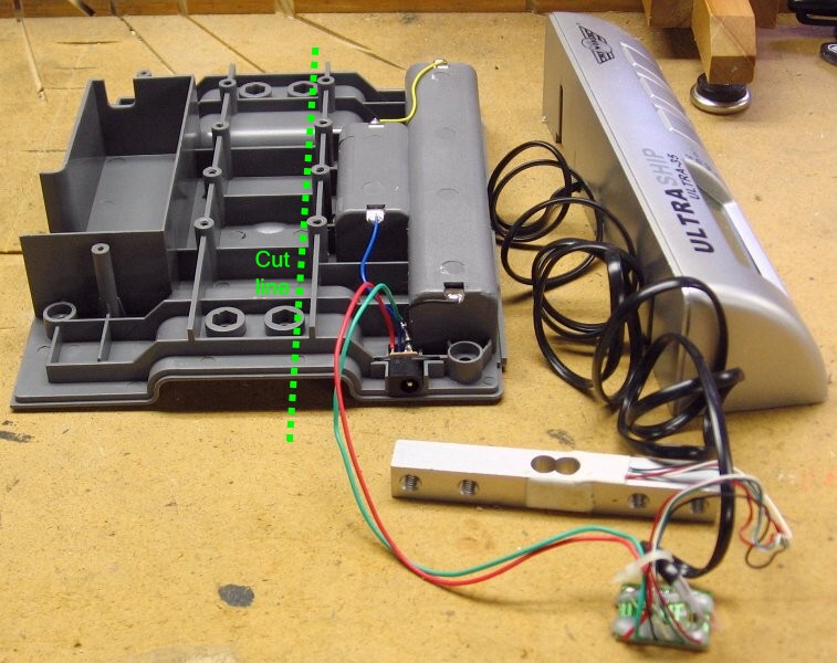 You
now have a large plastic piece wired to the connector board, the load
cell, and the display/control unit. The only useful part of the large
plastic piece is on the right side (originally the rear), where we find the battery
compartment and the jack for the AC adapter. Everything to the left of
the green line is superfluous for the NF4, so we are going to cut it
off.
You
now have a large plastic piece wired to the connector board, the load
cell, and the display/control unit. The only useful part of the large
plastic piece is on the right side (originally the rear), where we find the battery
compartment and the jack for the AC adapter. Everything to the left of
the green line is superfluous for the NF4, so we are going to cut it
off.Cut the plastic base at the green line, making sure as you cut that everything to the right remains intact. I used a radial arm saw with a 10-inch 40-tooth carbide tip blade. I'm sure a table saw would work as well. A finer tooth blade might give a smoother cut, but there is nothing wrong with the cut I got from the 40-tooth blade.
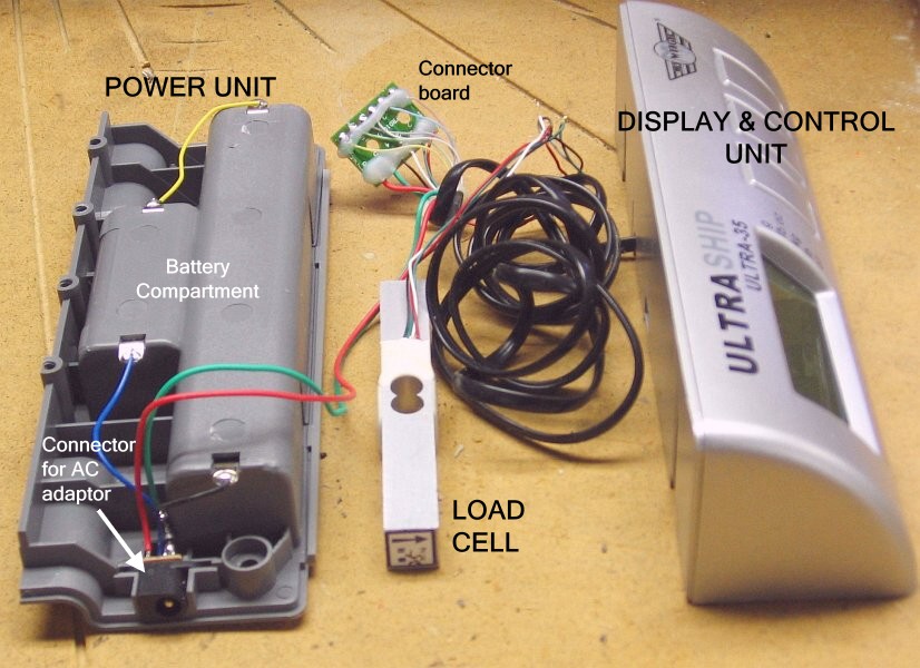 The
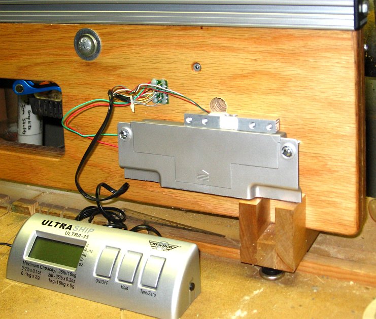
disassembly of the digital scale is complete. You now have four pieces:
The
disassembly of the digital scale is complete. You now have four pieces:- The power unit will be mounted behind the backer board. It contains the batteries and the connector for the AC adapter.
- The connector board will also be mounted behind the backer board, near the power unit.
- The load cell will be mounted on the front of the backer board, so that rotation of the backer board will flex the beam and create a reading.
- The display/control unit is at the end of a coiled cable, and can be placed wherever you find it convenient.
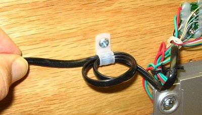 In
real-world use, there may be an occasional rude yank on the coiled
cable to the display/control unit. You don't want the strain to be felt
where the individual wires are soldered to the connector board. So we
provide "strain relief", in the form of a 1/4" plastic cable clamp.
In
real-world use, there may be an occasional rude yank on the coiled
cable to the display/control unit. You don't want the strain to be felt
where the individual wires are soldered to the connector board. So we
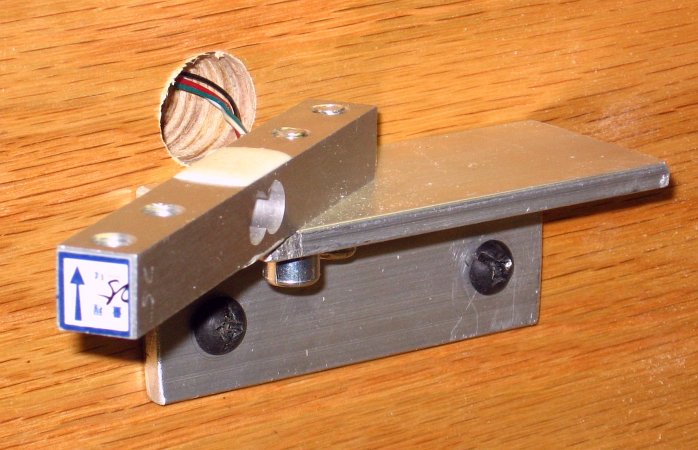
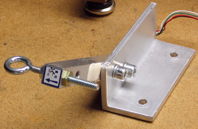
provide "strain relief", in the form of a 1/4" plastic cable clamp.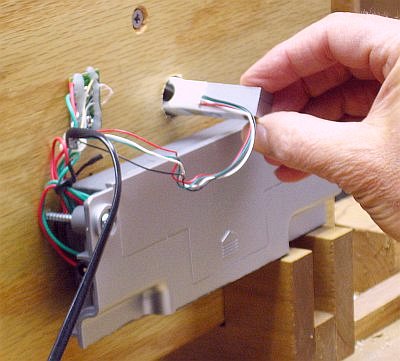 Slip the load cell beam
through the 3/4" hole as shown. It should go arrow-end first.
Slip the load cell beam
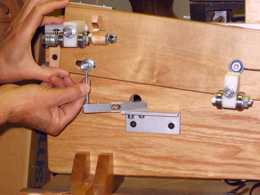
through the 3/4" hole as shown. It should go arrow-end first.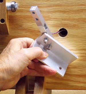 Mount the load cell
to the aluminum angle, as you did before. But this time, it's
permanent. If you had to enlarge hole "B" earlier, be sure you orient
the load cell beam properly in the hole.
Mount the load cell
to the aluminum angle, as you did before. But this time, it's
permanent. If you had to enlarge hole "B" earlier, be sure you orient
the load cell beam properly in the hole.